
Appearance
Assemblies and products
An assembly is an element's layer build-up: the framing, insulation, linings, cladding and cavities that give a wall, roof or floor its construction R-value. This page covers building your own assemblies, choosing products, and swapping products live from the H1 page.
You started with a sample - now build your own
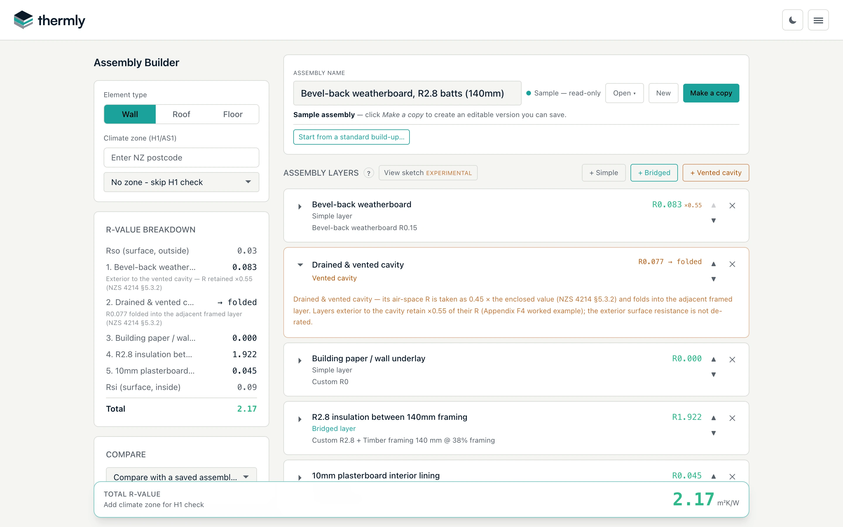
Every element needs an assembly, so Thermly ships sample assemblies for walls, roofs and floors to get you a result immediately. They appear alongside your saved assemblies and are read-only - open one to see its build-up, and click Make a copy for an editable copy of your own. When you are ready to reflect the real construction, you build your own. It is the same short, layer-by-layer form. Each sample is named for what it is, insulation included - "Bevel-back weatherboard, R2.8 batts (140mm)", for example - because that figure is what tells one sample from the next.
Open the Assembly Builder from the nav or from New assembly on the Dashboard.
Start from a standard build-up
The fastest way to a real assembly is the guided Start from a standard build-up flow under the assembly name: choose Wall, Roof or Floor, then a construction group, then the specific build-up. The library holds 64 build-ups in eight groups - Timber frame, Steel frame and Mass and panel walls; Roof space, Skillion and Low slope roofs; Suspended and Slab on ground floors - and every entry's name carries the things that change the answer: the cavity state (a drained cavity triggers a different calculation from a direct-fixed wall) and the framing material (steel routes through a different method from timber). Framing depth is not a separate build-up to hunt for - you pick the member on the layer, and all timber and LVL depths are available in walls, roofs and floors alike.
Every insulation slot ships empty, deliberately: a build-up is a starting point, not a claim about what is in your building, so no generic entry pre-selects an insulation product, promises an R-value in its name, or names a manufacturer.
There is one declared exception. Where a build-up is a manufacturer's proprietary structural system, with no generic twin to offer instead, the entry says whose system it is and arrives with that product in place. Today that means nine Formance structural insulated panel build-ups, spread across the wall, roof and floor groups. The exception is narrow - that brand, in those entries only - and the arithmetic does not change: the manufacturer's published figure for the panel is one input, and Thermly still calculates everything around it (surface resistances, cavity, cladding, lining and the timber bridging the panel) by NZS 4214. See Structural insulated panels.
The three Slab on ground entries (a plain slab, a generic raft, and a floor with a manufacturer-supplied R) are signposts rather than build-ups - a slab's R-value is dominated by ground coupling, not a layer stack, so they route you to the Appendix E lookup or the supplied-R route (see Supplied floors and rafts).
Applying a build-up works as a guided template. The scaffold layers it pre-fills - cladding, underlay, lining, cavities - are locked read-only, while the decision layers (your insulation pick and framing configuration) stay open and are marked "Your choice". A Customise layers control unlocks the whole stack at any time for free editing, and the assembly keeps a build-up breadcrumb showing where it started, including after saving and reopening.
Add layers
Build the element up layer by layer (the order is preserved and shown on the report). Each layer is one of:
- Simple layer - a single material: a lining, a cladding, a rigid board, an air gap. Pick a Product from the catalogue, or choose Custom R-value and type an R directly.
- Bridged layer - insulation between framing, calculated by the isothermal-planes method. You set an insulation product and a framing product (or custom Rs) and the framing fraction - the proportion of the layer's face taken up by framing. This is the standard timber- or steel-framed wall, or a rafter or joist layer.
- Vented cavity - a drained and vented cavity behind cladding, handled per NZS 4214 §5.3.2.
A layer of continuous insulation over the framing - a rigid board or insulated rigid air barrier running across the studs - is not simply added in series. H1/AS1 6th edition §2.1.3.2 requires it to be carried inside the framed portion (its R counted in both the framing path and the insulation path), a layer between two framed portions to be split half into each, and a pliable membrane or underlay to be treated as if it were not there. Thermly applies all three, and each affected layer says so on the report - so a wall insulated over the top of its frame is credited the way the Acceptable Solution prescribes.
Which treatment a layer gets is something you declare, because the fold reads higher than the series sum and so must never be guessed. Every simple layer carries a Role in the framed build-up control with three settings, each explained in a line under it: None (an ordinary layer, counted in series), Continuous insulation (included in the framed layer beside it, §2.1.3.2(i)) and Pliable membrane or underlay (treated as absent, §2.1.3.2(iii)). The built-in build-ups arrive with their roles set; a layer you add yourself starts at None. When you pick a rigid insulation board (EPS, XPS, PIR, phenolic, wood fibre) onto a layer that has no role yet and sits next to a framed layer, Thermly sets the role to continuous insulation for you and says so on the card - change it if the board does not run unbroken over the framing. A role you have chosen, including an explicit None, is never changed for you, and a saved layer is never changed on opening. A layer marked continuous insulation shows a FOLDS chip and its R-value badge reads "R1.000 → folded" rather than a zero, so the value that moved into the framed layer is still on the page; the R-value breakdown and the report's build-up card say the same.
Surface resistances (the internal and external air films) are added by Thermly automatically at the compliance values - you do not enter them. The layer card shows a running R-value as you complete it, and the header shows the assembly total. Completed layers collapse to a one-line summary (products, framing fraction, R-value) - click to expand - and any advanced setting that changes the calculation shows as a small chip on the layer header, so nothing is hidden by collapsing.
A note on colour: a computed R-value shows green only when the engine returned it unflagged. A total that carries a caution (for example, a configuration the one-dimensional method can only treat as indicative) takes the amber or red of its warning, so a number in doubt never reads as reassurance.
The framing fraction and the 38% rule
For a framed wall, H1/AS1 6th edition sets a default: assume a wall framing fraction of no less than 38% unless a lower fraction is demonstrated for the building (§2.1.3.1(a)(i)). Timber conducts far more heat than the insulation between it, so understating the framing overstates the wall's R-value.
The Assembly Builder helps you get this right:
- A one-click H1/AS1 min (38%) button sets the compliant default.
- A Framing layouts… menu (Steel layouts… on a layer with a steel section) fills the bay calculator from a named configuration (for example 45 mm studs @ 600 + dwangs @ 800) and applies the derived fraction in one click; the menu then shows the layout you picked. Wall layouts always include a 10% openings-and-junctions allowance, so the one-click figure is an all-timber estimate rather than the bare single-bay minimum.
- A built-in framing-fraction calculator works it out from member spacing, width, dwangs or blocking and an openings-and-junctions allowance, or as an area-weighted average across wall panels. Its bare single-bay result is labelled "Single bay (select set)" - the minimum framing set, not a compliant wall value.
- If you set a wall below 38% without a demonstration, Thermly warns: "Below the H1/AS1 6th edition 38% framed-wall assumption. Use 38% unless project records demonstrate a lower framing fraction is appropriate." A sub-38% figure taken from a bare single-bay calculation with no openings allowance carries the same caution, because a single bay excludes the extra timber that packs up around openings, corners and junctions.
- If you genuinely hold a lower figure - a frame-and-truss supplier's timber-percentage report for this build, or a whole-wall take-off from the consent drawings counting lintels, sills, trimmers, corners and junctions - you can record the demonstration under the caution. It is deliberately not a checkbox: you write what the evidence is (a nominal bay layout does not qualify, and the form says so), and that text prints verbatim in the report's framing-fraction declaration. Changing the fraction afterwards clears the declaration, since a demonstration is of a specific figure.
- On a project with traced walls, Thermly can make that demonstration from the plan. On the H1 page, open the wall's Edit assembly in this report bar; beside the framing fraction, which names where its figure came from (the H1/AS1 default, a take-off, the declared framing, or entered by hand), Calculate framing fraction… opens a Framing take-off. It counts the framing in each wall that uses the construction - studs, top and bottom plates, nogs, jamb studs, heads, sills, cripples and corner studs - from the wall's traced length, stud height and openings, over the net wall area. You set the layout (stud and nog spacing, jamb studs each side, extra studs per corner and, for timber, the lintel depth, each from a preset or typed), and Apply writes the area-weighted fraction to every one of those walls with a sentence stating the method and layout, which the report prints as the demonstration.
The report declares every framed layer's fraction and its basis - declared geometry, the 38% default, or a typed value - and, where an air gap or continuous insulation was folded into the layer, prints the exact equation the engine evaluated, so the printed inputs reproduce the printed R.
Roof and floor framing is not subject to the 38% wall rule; H1/AS1 sets no framing default for them, so a roof or floor fraction is only as good as the geometry behind it - which is why the built-in roof and floor build-ups carry their take-off (member width, spacing, bay length) as data the report can state. The Framing layouts… menu covers roofs and floors too, with the common NZ members one click away: solid and LVL rafters and joists, engineered I-joists and open-web joists, purlins and battens.
Steel framing is supported: add a light-gauge steel section (base metal thickness, flange width, section depth) and Thermly applies the NZS 4214 metal-frame method. You can pick a published section instead of typing the three numbers - the catalogue carries fifteen supplier-sourced light-steel sections (the 89 × 41 × 0.75 mm standard stud, a 150 × 41 × 0.75 mm rafter-range section, a 150 × 45 × 1.6 mm mid-floor joist, a 300 × 100 × 1.75 mm deep section for floors and roofs, a range of ten proprietary floor joists from 150 to 290 mm deep and, for roofs, a 35 × 38 × 0.55 mm top-hat ceiling batten, each citing the product technical statement, BPIR declaration, construction manual or supplier schedule it came from); picking one fills the dimensions and keeps the link on the layer as the section's provenance, which the report cites (the build-up card names the section record and the supplier document it came from), and editing a dimension by hand clears that link. Each option states its depth, and the panel says so when a pick changes the depth your layer had. The built-in steel build-ups and the four steel walls and two steel roofs in the default library all use these sections rather than a nominal. The 38% wall floor applies to steel-framed walls exactly as to timber - clause 2.1.3.1(a)(i) names framed walls, not a material - and a section missing a dimension reports no R-value at all rather than quietly falling back to something else. A steel layer can also carry a strip thermal break - EPS or similar strips between the framing and the cladding, the NZS 4214 §5.7.4 / Appendix F3 configuration: the metal path then counts the strip plus the standard's two contact resistances, strip coverage beyond the member faces counts as its own parallel region, and the "Strip thermal break, steel frame, direct-fixed" build-up in the Steel frame group ships with it set up. The break material picker offers the 10 mm EPS strip at R0.25 - the minimum E3/AS1 clause 1.1.4(d) requires at the outside face of every steel framing member in a house, the value that clause itself states for a 10 mm strip - alongside the 12 mm F3 strip (R0.29) and a 15 mm EPS sheet (R0.36), for walls, roofs and floors alike, so a steel roof or floor layer can declare its break too. A steel wall that fails bare (R0.43 at 38% framing with R2.8 between C89 studs) passes with the 10 mm strips (R1.05), and reaches R2.48 where the break is a continuous 40 mm sheet instead - the default library ships both forms of that wall, and both forms of the steel garage-boundary wall, so the pair can be compared directly. A continuous board running unbroken across the whole frame face can be entered two ways, and both put its R on the steel path and the insulated path alike. Declared on the steel layer as its thermal break with the coverage set to 100%, it is the NZS 4214 §5.7.4 / Appendix F3 break over every member, so the metal path also takes the standard's two contact resistances; this is how the library's "Continuous rigid board, steel frame, drained cavity" build-up carries its board (R2.57 with an R1.2 board over R2.8 batts). Modelled instead as its own layer with its role set to continuous insulation, it is folded into the steel path under H1/AS1 §2.1.3.2(i), which declines those contacts and so reads slightly lower (about 0.06 on that wall); the default library's two 40 mm sheath walls are entered this way, and so is an insulated rigid air barrier on a direct-fixed wall. Enter a board once, by one route or the other. Because E3/AS1 clause 1.1.4(d) puts the break at the outside face of each member, a sheet of at least R0.25 between the steel and the cladding IS that break: the review rail does not ask for strips as well, and the report's steel card prints "Thermal break: continuous sheath …, R x.xx (folded per H1/AS1 §2.1.3.2(i))". A sheet on the inside of the frame, between the steel and the lining, still folds for H1 but is on the wrong face for E3, and the rail says so. If you declare a strip break on a layer that already folds an adjacent insulation sheet, the layer panel and the result both warn that the same sheath declared twice is counted twice (R1.16 becomes R1.77 with the catalogue's 15 mm R0.36 sheet); keep the break only where the strips are a separate layer beneath a separate board. Where a steel batten bridges continuous insulation (a top-hat or Z-girt over rigid board), Thermly warns that the one-dimensional transform is optimistic and that a two-dimensional determination (THERM / ISO 10211) is required for a compliance figure. On a house, the review rail also raises an issue for any steel wall or roof layer that carries none of the three things the clause accepts at R0.25 or more - a declared strip break, a continuous insulation sheath at its outside face, or insulation running over and covering the member: E3/AS1 clause 1.1.4(d) requires the break on each steel framing member and allows any material or method that provides R0.25, so declare the one the framing actually carries - strips on the layer, the sheet's role, or the layer's insulation thickness against its framing depth - or specify one. The report itself states the break, or "none declared", on every steel layer's build-up card as a plain fact. See How Thermly calculates compliance.
Steel roofs. The same strip break is what carries a light-steel skillion: the "Profiled metal, steel rafters, EPS strip break" build-up in the Skillion group ships 150 × 41 × 0.75 mm rafters at 600 crs with the 10 mm EPS strip (R0.25) over each flange at the frame supplier's 56 mm coverage, and reads R2.67 with R3.6 between the rafters - over the clause 2.1.2.11 roof minimum of R2.6 that the same rafters cannot reach bare (R1.67, and no amount of insulation between them gets past R2.59; the bare entry ships last in the group and says so). Deeper batts keep paying with the strips in place (R2.84 at R4.0, R3.21 at R5.0), while R2.8 fails at R2.29. Set the measured strip coverage on your copy: coverage left blank claims the flange faces exactly (R2.67 either way at this section). The default library carries the matching "Skillion, R3.6 between 150mm steel rafters, EPS strip break". A trussed steel roof is different: the ceiling insulation runs over and covers the bottom chords, so no chord strip is declared - and that cover is what answers E3/AS1 1.1.4(d) at the chord itself. The clause asks for a thermal break of at least R0.25 at the outside face of each steel framing member, names 10 mm EPS strips as one material that provides it, and adds that other materials or methods may be used; insulation lying over the member is one of those methods, so the review raises no "no strip thermal break declared" issue once the layer records an insulation thickness greater than the framing depth (a custom R typed with no thickness has no cover to read, so the layer is bridged full depth and the issue stands until a thickness is recorded). The packer between each truss heel and the wall top plate is the separate junction detail, outside the construction R, for where the insulation cannot cover. Do not add a chord strip to clear the review - it would model a strip that is not built. "Steel trusses, R5.0 over 89mm bottom chords" in the default library reads R5.08 with the chords at 1.2 m centres (the frame supplier's truss spacing) bridging only the bottom 89 mm of a 225 mm batt. The 136 mm of batt above the chords is the same layer carrying on over the member, so under H1/AS1 §2.1.3.2 it stays inside the bridged portion and is counted in both the framing path and the insulation path, not added in series after them; that is where a steel truss ceiling earns its R, because a steel chord has almost no resistance of its own (bridged full depth the same layers read R2.02). That 136 mm is R5.0 x 136/225 = R3.02 sitting at the chord's outside face, twelve times what clause 1.1.4(d) asks for there. A light-steel ceiling batten (the 35 × 38 × 0.55 mm top-hat section) is picked on a roof layer like any other section, and its Steel layouts menu offers the 400, 450 and 600 mm centres its declaration states, with the 38 mm crown as the bridging face.
Separately from the framing rules, H1/AS1 §2.1.2.11 sets a minimum construction R-value for every envelope element (roof R2.6, wall R1.0, suspended floor R1.3). An assembly below its minimum raises a blocking finding - stronger than a caution, because the figure is trustworthy and still not good enough, in any climate zone, with no way to trade it back elsewhere. It leads the warning rail in the builder and the Critical review items on the report.
Advanced NZS 4214 inputs
A bridged layer's occasional inputs live behind its Advanced menu; each is off by default, applies only when its values are complete and in bounds, and shows as a chip on the layer header while active. The menu names each with a short gloss - "Strip thermal break (steel framing)", "Chord penetration (partial-depth framing)" and so on:
- Steel section / bridging conditions - the light-gauge steel transform described above, with a Published section menu that fills the dimensions from a sourced catalogue section, and a checkbox to declare a ventilated through-bridge (NZS 4214 §5.7.2): a member passing through a vented cavity, such as a top-hat batten spanning a drained cladding cavity. Thermly computes the value but raises the note that the one-dimensional method does not apply to that case.
- Strip thermal break (§5.7.4 / Appendix F3) - for a steel layer only: pick the break material (or type its R) and, optionally, the strips' total coverage of the layer face. The metal path counts the strip plus the standard's two frame-facing contact resistances (0.03 m²K/W each, Appendix F3's own values); coverage left blank claims the member faces exactly, the minimal reading. Declared on a layer without a complete steel section, the layer reports no R at all - the break is never silently dropped. Declared on a layer that also folds an adjacent continuous insulation sheet, it raises the double-count caution described above.
- Structural insulated panel (not a framed wall) - declares that the layer is a panel bridged by its own timber, not a framed wall. See Structural insulated panels.
- Bounding enclosed air gap (§5.7 / Appendix F2) - an unventilated cavity sitting directly against the bridged layer (the brick-veneer case), folded into both the framing and insulation paths rather than counted as its own layer. Presets cover the wall (R0.17) and roof/ceiling (R0.14) cases.
- Chord penetration (§5.7) - where framing only part-penetrates the insulation (say 90 mm truss bottom chords under a 330 mm ceiling blanket), only the penetrated depth is bridged by the member. The insulation carrying on over the member is the same layer, so under H1/AS1 §2.1.3.2 it stays in the bridged portion and is counted in both the framing path and the insulation path; it is not added in series afterwards. A ceiling of this shape prints its working on the report, since its R cannot be reproduced from the batt and framing R-values alone.
- Compression check (NZS 4214 C2) - enter the insulation's nominal (labelled) thickness and the depth it is actually installed into; when the label exceeds the space, the insulation R is derated and the compression caution appears on the result and the report. Simple layers carry the same check.
- 2-D / measured override (§5.1.1(b)) - enter a THERM / ISO 10211 or measured (guarded hot box) effective R with a provenance note, and it supersedes the calculated value for that layer. The layer is marked externally determined on the report, carrying its provenance - the supported route for a configuration the one-dimensional method cannot certify.
One more input sits outside that menu, in plain view under a bridged layer's insulation: Still air gap on insulation path (NZS 4214), an enclosed gap counted in series with the insulation between the framing. Its presets are the NZS 4214 Table E3 values: R0.17 for a wall or floor gap of 20 mm or more, R0.14 for a roof or ceiling, and R0.20 for a 90 mm joist cavity with heat flowing down.
Structural insulated panels
A structural insulated panel (SIP) wall is not a framed wall: there are no studs at regular centres, only the timber that joins and trims the panels. Model one as a bridged layer whose insulation is the panel product, then open the layer's Advanced menu and tick Structural insulated panel (not a framed wall). A PANEL chip on the layer header shows the declaration is active.
The declaration lifts the 38% wall framing default, which is written for framed walls. It only takes effect when the insulation slot actually holds a panel-system product; on any other product the calculation ignores it, the 38% default still applies, and the layer says so. Roofs and floors have no 38% default to lift, so the layer simply notes the fact.
The timber is still counted. On the H1 page, a wall build-up that holds a panel offers Count the timber in these panels…, which counts the timber in every wall using that build-up from its length, height, openings and corners - timber splines at the panel joints (insulated splines count none), top and bottom plates, the trimmers, lintel and sill at each opening, and corner studs - and bridges the panel with the area-weighted result. The report records that take-off, and says why the 38% default does not apply. A panel is always bridged over its full depth, so a panel layer does not offer the rafter and joist layouts that lay insulation over a member.
The nine Formance build-ups arrive set up this way, with the panel product in place. The panel's R is the manufacturer's published figure for the panel alone; Thermly adds the surface resistances, cavity, cladding and lining, and applies the bridging, by NZS 4214.
Choosing products
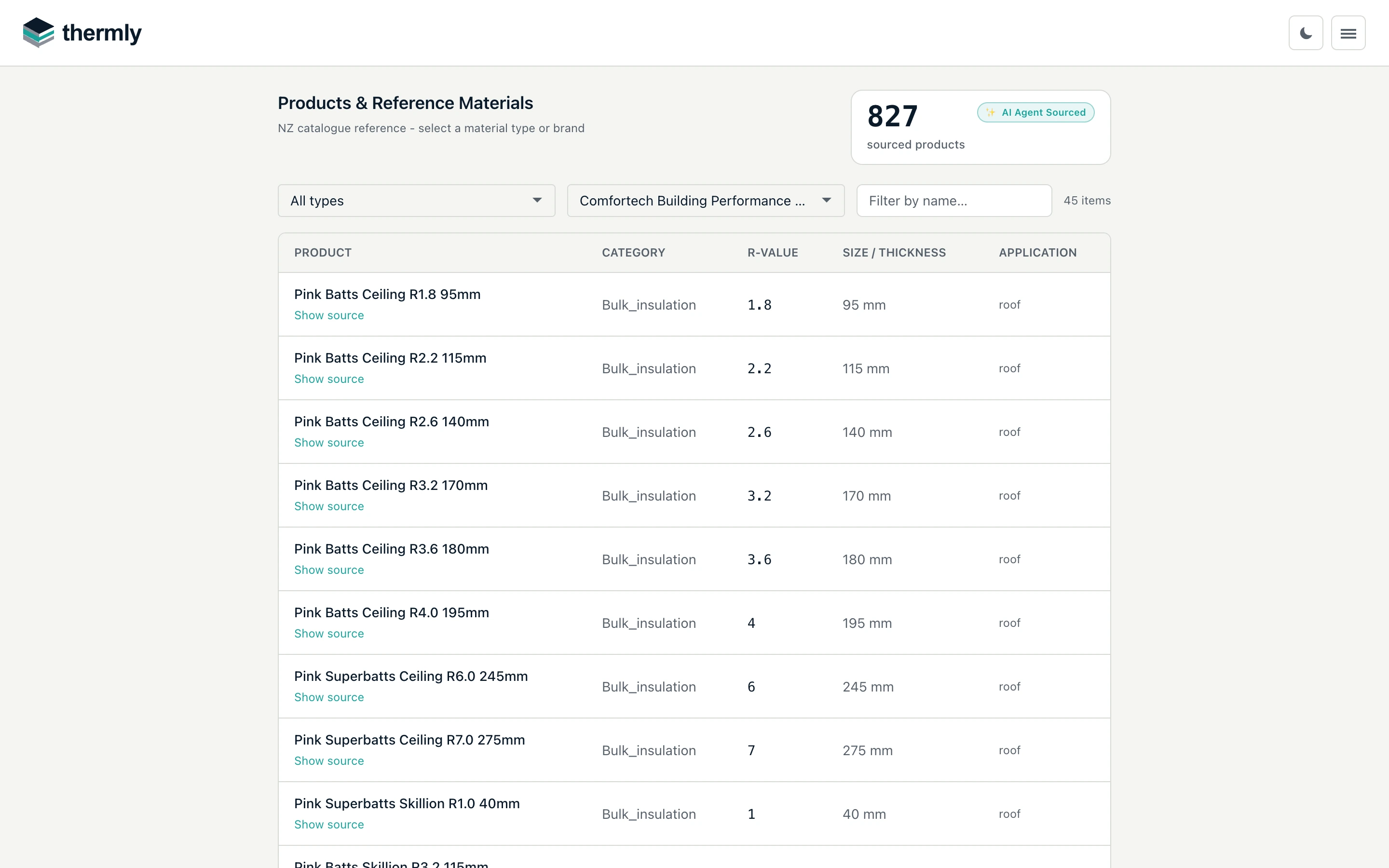
The Product picker searches the sourced NZ catalogue by name, manufacturer, category and common aliases (batts, foam, brick, and so on). A Brand filter leads it - narrowing to a manufacturer is usually the first step, so it sits first in reading and tab order. Reference materials (generic boards, timber framing, and the non-reflective enclosed air gaps from NZS 4214 Table E3) appear alongside branded products, badged Reference. There are no reflective (foil-faced) cavity rows: a building with foil insulation sits outside H1/AS1 (§1.1.2.1). Picking a product shows its catalogue R-value right on the layer row, and a slot only offers products that can actually be that layer - sheet linings (plasterboard, fibre-cement, plywood) are available as an outer skin too, which is what the garage side of an internal wall is made of.
Where a product's R-value is not published, choose Custom R-value and enter the figure yourself with its basis. Catalogue R-values are sourced from manufacturer datasheets and reference tables - see Product sourcing and provenance - and should be checked against the manufacturer's current datasheet before use.
Swapping products live from the H1 page
You do not have to leave the H1 page to try a different product. Each element on the compliance page carries its own copy of its assembly, so you can swap a product in place and watch the verdict recompute immediately. On any row with an assembly, a quiet full-width bar under the row - Edit assembly in this report, with the build-up's layer count - opens the editor in place, where you swap products, set custom R-values and rename the assembly and its layers, with each layer's computed R contribution shown inline. Click the same bar to close it again.
An unfinished build-up says so, loudly. A row whose assembly leaves a product slot unset shows a red notice naming every open slot and stating that the element is not finished. It matters: until the slot is set the build-up cannot be calculated, so the element is counted at the conservative §2.1.2.13 default of R0.18, which will usually fail the heat-loss check by itself. The notice carries the fix - Choose insulation… or Choose a product… - and the report bar names the same elements beside the verdict, so a FAIL caused by an unfinished row is not mistaken for a design that misses H1.
This is a capability the plan-linked workflow gives you: experiment freely. Try a higher-R batt, a different lining, a thicker cavity board; the heat-loss check updates live ("Recalculating…"), and you can see at a glance whether a change brings a failing element into compliance or buys headroom. It is the fastest way to find a build-up that works for the building.
Because the swap lives on this report's copy, it does not disturb your saved assembly library. The panel keeps the genealogy honest:
- unchanged: "a copy of [assembly] · swaps stay local to this report";
- changed: "modified from [assembly] · this report owns its own copy".
A row whose copy you have edited is marked Edited copy (with "source updated" added when the saved assembly has itself changed since). It is deliberately never re-pulled by itself, so a library change cannot wipe out a swap you made on purpose. ↩ reset from library discards the row's edits and takes a fresh copy of the source, with an undo straight afterwards. A reset touches only the assembly: the row keeps its area, name, colour, plan links and, above all, its openings.
You can rename the copy so the construction name on the report stays truthful after a swap. Thermly also watches for a label that has gone stale: where a layer's name states an R-value ("R2.2 insulation between 90mm framing") that the product now in the slot contradicts, the editor says so, the report prints the label without that figure, and Correct it rewrites just the stale figure in one click. Renaming a layer is only ever a relabel; it cannot move an R-value.
Some layers have no product to choose, and say why in place of a picker: a vented cavity (its resistance is method-derived), steel framing (sized by the NZS 4214 metal-frame method, not a product), or an externally-determined R that governs its layer.
Save and reuse
Save an assembly to reuse it across elements and projects; find your saved assemblies on the Assemblies tab of the Dashboard. A saved project keeps a snapshot of the assemblies it used, so an old report stays reproducible even after you refine the library. When a saved assembly has moved on since a row picked it up, the row shows an amber Assembly updated chip with Update to latest, and Update all refreshes every such row at once, build-ups included. A row you have edited into its own copy is left alone until you reset it.
Next
- Supplied floors and rafts - proprietary rafts and supplied-R floors.
- Generating your H1 report.