
Appearance
The plan take-off
The plan take-off is where Thermly measures your building. You trace walls, roofs and floors off the calibrated plan, drop windows, doors and skylights onto the elements they belong to, and give each element its own colour so the drawing stays readable. The result is a measured, checkable set of areas and a marked-up diagram that goes into your report.
This is the workflow that sets Thermly apart from typing areas into a form: the geometry is explicit, openings net out automatically, pitch is applied to roofs, and every number traces back to something you can see on the drawing.
Prerequisite: upload and calibrate the plan first.
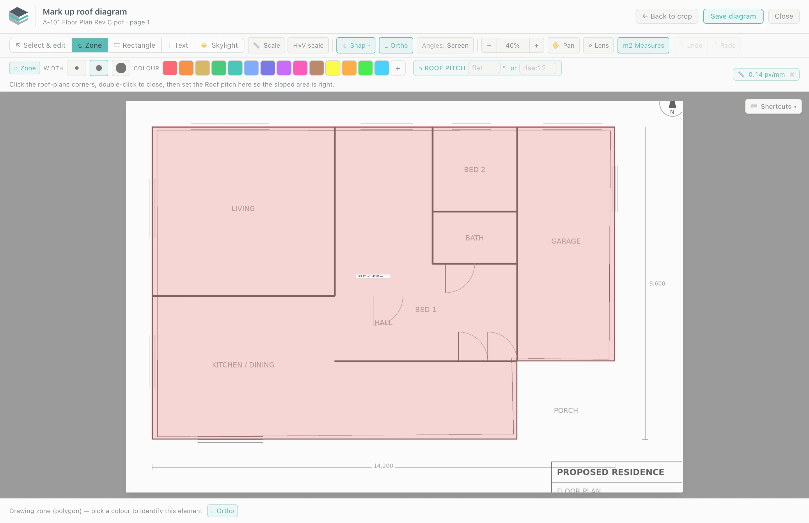
The toolbar
The tools across the top of the mark-up canvas. Each has a single-key shortcut (shown in the table) that fires when no run is in progress, so you can switch modes without a trip to the toolbar:
| Tool | Key | What it does |
|---|---|---|
| Select & edit | V | Select, move, reshape or delete a shape; click a placed opening to edit its size. |
| Zone | A | Trace an area by clicking its corners; double-click to close. For roofs, floors, and gross wall faces. |
| Rectangle | R | Draw a rectangular zone from two opposite corners. |
| Line | L | Trace a wall run by clicking along it; length × stud height gives the wall area. Walls only. |
| Split | X | Click a wall run to divide it into two independently-deletable sections; the click snaps to corners. Walls only. |
| Merge | M | Click the run you want to keep, then a run that meets it end to end, to fuse them into one section. Walls only. |
| Opening | O | Drop a window or door on a wall, then enter its width × height. Walls only. |
| Skylight | S | Drop a skylight on a roof, then enter its size. Roofs only. |
| Text | T | Place a text label on the diagram. |
The toolbar shows the tools that apply to the element you are taking off - Line, Split, Merge and Opening appear for walls, Skylight for roofs - and only the keys for tools the element offers do anything. Beside the tools sits the scale cluster: Scale (key: C) and H×V scale set the scale from a known dimension (see calibration).
Other controls: Snap (per-source options: your own drawn points - on by default, so closing a zone on its first corner or starting a wall where the last ended lands exactly on the vertex - plus intersections, plan lines and the detected grid, which are opt-in because snapping to geometry you did not draw is exactly when a point jumping off the cursor puts a trace in the wrong place; set your defaults under Settings → Plan markup, and Esc closes the menu), Ortho (the angle lock: it constrains lines to 0 / 45 / 90°; hold Shift to invert it momentarily) with an Angles: Screen / Relative toggle beside it (Screen snaps to the page's horizontal, vertical and 45°; Relative snaps in 45° steps from your last line, which is the one to use on a rotated plan), Pan, zoom (a marked-up plan opens fitted to the whole crop; the zoom chip toggles fit ↔ 100%), Lens (magnify under the cursor), m2 Measures (show area and length readouts), and Undo / Redo. A second, contextual row sits under the toolbar: it names the active tool and holds its options (the opening Type, the line-width and colour pickers, the roof pitch) plus a hint telling you what the tool expects. For a roof zone the hint reads: "Click the roof-plane corners, double-click to close, then set the Roof pitch here so the sloped area is right."
Closing a one-off zone immediately selects it for editing. Drag the filled zone to move it, drag a corner handle to reshape it, or double-click an edge to add another point. Click a handle to make it orange; Delete removes that point while keeping the polygon itself. A polygon always keeps at least three points. During an explicit batch take-off Thermly stays in Zone after each close so you can trace the next area without switching tools.
Prefer a side rail? Settings → Plan markup offers a choice of markup workspace: the default Classic toolbar described here, or an Alternative layout with a fixed vertical drawing-tool rail and grouped scale, view, legend and history controls. The choice follows your account and only rearranges the controls - drawing behaviour and saved annotations are identical. The same settings page holds your other starting points: the tool a diagram opens with, the line width, the text label colour and size, the length unit, whether Ortho, the magnifier and the measurement readouts start switched on, and the legend's corner, size and font size.
Walls
Select the Line tool and click along each wall run, double-clicking to finish. Thermly multiplies the run length by the stud height to get the gross wall area. Trace the gross face; you cut the openings out next.
Editing a run: extend, split, delete a section
A wall traced as several runs is made of sections, and the windows and doors you place bind to the run they sit on - so you can revise one part of a wall without disturbing the rest:
- Extend - select a line and use the ◀ Extend / Extend ▶ buttons to keep drawing it from either end (click to add points; double-click or Enter to finish). The line keeps its identity - its take-off row, assembly and openings are preserved - and its length re-syncs to the longer run. No more deleting and redrawing a wall just to make it longer.
- Split - with the Split tool, click a run where you want to divide it and it cleaves into two independently-deletable sections (the click snaps to corners, so an L-shaped run splits cleanly at the bend). Splitting never changes the wall: both halves keep the same construction and compliance row, and each opening re-pins to whichever section it now sits on.
- Merge - the reverse of Split, for a wall that ended up drawn in several strokes. With the Merge tool, click the run you want to keep, then click a run that meets it end to end to fuse them into one section; keep clicking to chain more in (a selected line also offers ⋈ Merge… beside its Extend controls). The merged run keeps the first run's colour, H1 row and openings - and adopts the other run's row when only it was linked. Merge refuses two runs that do not actually meet (bridging a gap would invent wall length; close it with Extend first) and two runs on different wall rows (recolour one to match the other first). One undo puts both runs back.
- Delete a section - select one run and delete it, and only that section (its length, and the windows and doors on it) is removed; the wall's other runs and their openings stay. Deleting a wall's last run removes the wall and its openings together, and undo restores them together. Deleting an element's row in the form view likewise strips its plan geometry, so the form and the plan never disagree.
Wall take-off assist
On a calibrated vector PDF (a drawing with real line-work, not a scan), Thermly can read the wall geometry for you. Switch on Wall take-off assist under Settings → Plan markup, then, with the Line tool active, press the Wall assist button on the toolbar: hover the inside face of a wall and the complete straight run lights up as a preview - joined across window and door gaps, stopped where it meets a crossing wall - and one click adds it through the normal wall workflow. Press Tab before placing to switch to the paired (opposite) face.
Every proposal lands as a standard, visible wall line - editable, extendable and undoable like anything you drew by hand. The button is a true toggle: press it again (or Esc) to return to manual drawing mid-take-off. Detected wall-face corners also get snap priority when the Plan lines snap source is on, so manual Line and Zone clicks land on real corners. Scanned and outline-only plans keep the manual tools - Thermly does not guess where a wall might be.
Raking walls
A gable end, a wall under a mono-pitch roof, or any wall whose stud height changes along its length is a raking wall - length × a single stud height would get its area wrong. For these, start from the From your plan buttons at the top of the Walls section on the H1 page with 📐 Raking wall (instead of ✏️ Draw and the Line tool).
Draw on a side-on elevation (a plan sheet or elevation that shows the wall's true profile), not the floor plan. Outline the wall's shape by clicking its corners and double-clicking to close, exactly as you would a zone. Thermly takes the wall area straight from the traced polygon, so a sloping or stepped top edge is measured as-drawn - there is no stud-height multiply. A traced wall carries a 📐 Raking profile badge so you can tell it apart from a length-based wall run at a glance.
Everything else works the same: it takes a plan colour and a tag like any wall, its assembly is assigned from its element row in the form, and you drop windows and doors on it with the Opening tool - they net out of the raking wall just as they do a rectangular one.
The framing take-off
Your traced walls also feed a framing take-off. From a framed wall's build-up on the H1 page, Calculate framing fraction… counts the framing in each wall that uses that construction - studs, plates, nogs, jamb studs, heads, sills, cripples and corner studs - from the wall's traced length, stud height and openings, and records the area-weighted result as the framing fraction demonstrated for this building. See the 38% rule.
Roofs and ceilings
Select Zone, click the roof-plane corners, and double-click to close. Then record the Roof pitch, either in degrees or as a rise:run (for example, 3:12). The measurement label shows both the sloped and plan areas, for example "45.50 m² ∠30° (plan 39.40 m²)" (sloped area = plan area ÷ cos(pitch)), so the conversion is auditable.
Which of the two areas counts for heat loss is a separate choice, because it depends on where the insulation is, not on the roof's shape. Each roof row on the H1 page has a Ceiling follows pitch tick box beside its Pitch field:
- Off (the default) - a flat ceiling under a pitched roof, as with a trussed roof. The insulation lies on the flat ceiling, so the heat-loss area is the plan area. The pitch is still recorded, and the row reads, for example, "flat ceiling - heat loss uses plan 39.40 m² · 45.50 m² sloped roof".
- On - the ceiling follows the rafters: a skillion or cathedral ceiling. The insulation follows the slope, so the heat-loss area is the larger sloped area, and the row shows the plan area converting to it.
Tracing a pitched roof on the plan therefore takes the flat footprint into the row and records the pitch; tick Ceiling follows pitch to switch the row to the sloped area. Both reports disclose the choice per roof: a pitch that was counted shows its plan-to-sloped conversion, and one that was only recorded is marked with an asterisk.
Floors
Trace the floor with Zone or Rectangle. A cut-out drawn inside a floor zone is always a void (a stairwell, a garage you are excluding) - a window belongs to a wall, so a floor never offers window or door cut-outs that would quietly move floor area into the building's glazing. For a slab-on-ground or a proprietary raft, the floor's R-value comes from a wizard rather than a layer stack - see Supplied floors and rafts.
Derive the roof and floors from your walls
Once the envelope walls are traced, you usually do not need to trace the roof or floor at all. The 🧱 From walls button among the From your plan buttons of the Roofs, Slab-on-ground floors and Other floors sections finds the region(s) your traced walls enclose and turns each into a take-off diagram and schedule row - no re-cropping, no re-tracing. Because walls are traced along the inside face, the derived area is already on the internal-dimensions basis H1 measures.
The preview shades every closed region found on each wall diagram - a garage split off by its boundary wall shows as its own region - and you tick the ones that are thermal envelope. A region can instead be minted as take-off only (shaded violet): it gets a diagram and quantities for the insulation take-off but stays out of the H1 calculation - the garage's own ceiling, priced as a client option, is the classic case. Where a loop does not close, the open run ends are pinned on the preview so you know exactly where to nudge. An internal courtyard bounded by its own walls is cut out of the derived area automatically.
The derived diagram reuses the wall diagram's exact crop and scale, and stays fully editable in plan view - punch out a void, trim a porch, and the linked row keeps in sync like any drawn zone. Multi-storey plans need no setup: derive the floor from the ground-floor plan and the roof from the top-storey plan. For a slab row, the slab lookup also pre-fills its area and perimeter from the derived polygon.
This walls-first workflow is why the Wall section now leads the building-elements schedule on the H1 page (the report keeps its conventional order).
Openings: windows and doors
With the Opening tool, choose Window or Door, then click the wall to drop it. Enter its width × height in the inline panel; a live readout shows the area in square metres. Each opening is subtracted from the wall it sits on - the wall's element row shows the net area - so your net wall area is correct without separate arithmetic. Openings carry an auto tag (W1, D2, and so on) that you can edit to match the plan's numbering, and an optional name. Tags are plain numbers: if two openings resolve to the same number, the clashing one bumps to the next free number and its row in the form is flagged amber with a tooltip, so a clash never silently merges two openings.
Sizes prefill from the plan's own text. On a PDF with a text layer, dropping an opening beside a call-out such as "W7 600 × 1,200" or "D2 810 × 1,980" opens the panel with the number and size already filled - you check the values and click Place. A door with no call-out nearby starts at a standard single leaf (810 × 1,980 mm) with a note saying so; windows start blank, since there is no stock window size to assume. A door is never sized from a window's call-out or vice versa. The read uses the PDF text layer locally in your browser - no AI call, nothing sent anywhere - and image-only plans simply keep manual entry. It is on by default; turn it off under Settings → Plan markup ("Prefill window and door sizes from plan text").
Or from the window and door schedule, by number. Most plan sets put the sizes in a schedule, not beside each unit. Once the panel holds the opening's plan number, Thermly looks that number up on the plan's own window and door schedule (read when the plan was uploaded) and fills the width and height, with a line saying where the figure came from, for example "W16 - 2,690 × 1,500 mm from the window & door schedule (p20)", and whether AI read it. On a set with no schedule sheet, the sizes written beside each unit on the floor plans and elevations are used the same way, and named as sizes marked on the plan. The lookup only ever fills a blank field, a door's assumed standard leaf, or its own earlier fill: it never overwrites a size you typed or one read from a call-out. Check it, then Place.
Or with no size at all. Place stays available with both size fields blank (a half-typed size still cannot be placed), so where a plan prints only the tag beside a window you can mark every opening on a first pass and size them later. The same goes for skylights. An unsized opening is flagged, never silently dropped: it wears an amber ? on the plan, its row in the form carries a "No size yet" note, and a banner lists it by tag and parent wall or roof. Because an opening with no area would leave its wall reading as solid, Thermly will not generate a report until every opening is sized - the report bar names the ones outstanding.
You can also cut an opening out of a zone by drawing it: with a zone selected, use Cut as to trace a window, door or void polygon inside it. The zone's label shows the deduction, for example "32.40 m² − 2 openings · 24.00 m".
Windows and doors stay within the wall envelope as glazing and door area: Thermly nets them from the opaque wall and counts them in the glazing and door buckets of the heat-loss check.
Skylights
With the Skylight tool, click the roof and enter the skylight's true in-plane size (the sloped width × height, not pitch-corrected). Skylights net out of the roof and roll into the roof-plus-skylight bucket of the reference calculation. Skylight R-values get specific treatment under Appendix D - see How Thermly calculates compliance.
Colours, tags and names
Each wall, roof and floor carries its own colour on the plan. Pick one from the palette and trace; you can recolour any time, on the plan or from the colour dot on the element's row in the form, and new elements are born with the first unused palette colour so they stay visually distinct. The palette - ten high-contrast defaults, plus four fluoro highlighters that punch on screen but print faint on a report - is yours to edit under Settings → Plan markup, and it follows your account across devices. On Chrome and Edge the form's colour picker can also match a colour on screen: an eyedropper for sampling the exact colour off a plan image marked up in another product.
Elements also carry an auto tag and optional name - WA1 for walls, RO1 for roofs, FL1 for slab-on-ground floors, SF1 for suspended floors - with the number editable to match your drawings. The two-letter prefixes are deliberate: they cannot collide with the joinery tags an architect writes on a drawing (a wall W2 and a window W2 in one schedule is a real ambiguity Thermly avoids). The tag and name show in the plan caption next to the measurement, and the legend lists each element as, for example, "WA1 - North wall", so the plan, the form and the report all read the same identifiers. On the report, openings are identified by the element they sit in - WA1-W2 is window W2 on wall WA1 - with your own plan tag carried through after the hyphen.
Assemblies are assigned in the form view, from each element's row on the H1 page - not on the plan. Colouring or re-tracing an element never changes, or clears, the construction you picked in the form. See Assemblies and products.
Keyboard-driven drawing
The take-off is built to be driven fast from the keyboard. Single keys switch tools (V select, A zone, R rectangle, L line, X split, M merge, O opening, S skylight, T text, C scale) whenever no run is in progress - mid-run the whole keyboard belongs to the run, so a stray letter can never abandon a half-traced wall. While drawing a line or zone: arrow keys aim the next segment, type digits to set an exact length, Tab switches to entering a bearing - a typed bearing locks the direction while the mouse still sets the length, so you pull the angled segment out and click - U toggles mm / m, Enter places or closes, Backspace or ⌘Z steps back the last point, and Esc clears the typed entry first, then cancels the run when pressed again. The toolbar Undo button follows the same point-by-point behaviour. In Select & edit, arrow keys nudge (Shift for a larger step) and Delete removes the active vertex or, when no vertex is active, the selected shape. See the full list under Keyboard shortcuts, or press the ⌨ Shortcuts button on the canvas.
Legend and saving
Thermly builds a legend from your coloured elements (swatch, tag and name); drag it to reposition it, adjust its size, font and visibility from the toolbar's Legend menu, and set your starting defaults in Settings → Plan markup. The legend is drawn fresh wherever the plan appears, so recolouring, renaming or renumbering an element from the form later keeps the key in step with the elements it describes. On an alteration or addition the same is true of the shading that tells old fabric from new - hatched for existing and unchanged, cross-hatched for existing and altered, plain colour for new building work - which is drawn from each row's setting, marked in the legend, and explained by a key line under the plan. Click Save diagram to embed the marked-up plan in your report. Re-open and revise it any time - the Review button on a saved diagram opens it in a floating window you can drag aside while you keep filling in the form. Re-cropping a saved diagram is safe too: the drawing - shapes, cut-outs, calibration and legend - is re-anchored onto the new crop, so a typed 9.60 m wall is still 9.60 m after the change.
Next
- Give your elements real build-ups: Assemblies and products.
- See the numbers it produces: Reading the H1 report.